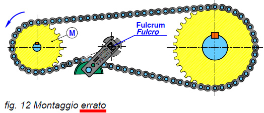
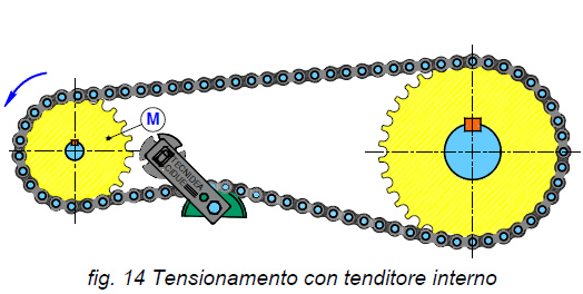
Roller chains (for transmission or transport) and belts are part of the series of mechanical systems called enveloping flexible elements which share the characteristic of reacting only to tensile stress. These mechanical parts are generally used to transmit power between two rotating hubs, but they may also be used to carry or lift objects. For a correct use of enveloping flexible elements, it is necessary, while designing, to contemplate a system for keeping these units always tensioned during operation. The wear of the parts of a chain (pins, bushes and rollers) in contact with each other during operation, creates a greater backlash and the relative stretching of the chain. When this is excessive it may cause: a smaller winding angle, lack of constancy in the transmission ratio, abnormal contact between the chain rollers and the teeth of the pinion, premature wear, high noise, vibrations, tooth skipping, escape of the chain from the transmission and, in extreme cases, breakage of the chain. It is therefore inevitable to equip the transmission with an automatic chain tensioner, to recover the stretching and constantly absorb vibrations. Automatic torsional chain tensioners must be placed on the loose part of the transmission, as close as possible to the drive pinion. They may be fitted either on the outside of the transmission (fig. 9) or on the inside (fig. 10), preferably the first option, if possible. Automatic rotational tensioners present a point of rotation, known as the fulcrum, where the tensioner arm works by tensioning the chain or belt. It is extremely important to put the tensioner in such a way that its fulcrum is never in the direction of the line of application of the chain force (fig. 12), so that it can never get stuck.
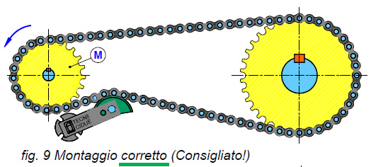
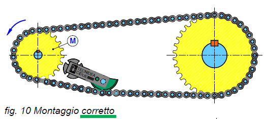
Automatic rotational tensioners present a point of rotation, known as the fulcrum, where the tensioner arm works by tensioning the chain or belt. It is extremely important to put the tensioner in such a way that its fulcrum is never in the direction of the line of application of the chain force (fig. 12), so that it can never get stuck.
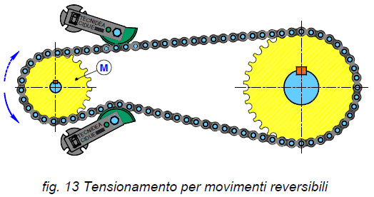
Nel caso di una trasmissione a doppio senso di marcia, dovrà essere posizionato un tenditore su entrambi i rami della catena all’uscita dal pignone motore (fig. 13). In questo caso si dovrà aver cura nel posizionare i tendicatena in maniera tale che quando agiscono, alternativamente, sul ramo teso della trasmissione non dovranno oltrepassare l’angolo massimo di lavoro consentito dall’elemento elastico, dovuto all’allineamento della catena in fase di tiro.
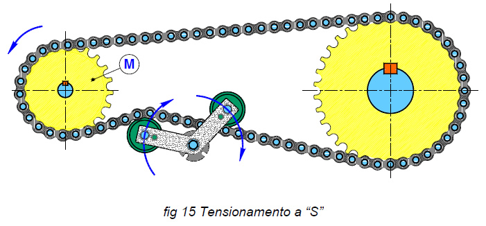
Nel caso in cui la trasmissione presenti un elevato interasse, spesso capita che un tenditore non abbia sufficiente corsa per recuperare tutto l’allungamento della catena, ma con un avvolgimento a “S” (fig. 15), fattibile solamente con i tenditori a rotazione, è possibile riuscirci con un unico elemento elastico.
In a chain or belt tensioner the most “delicate” point is the fulcrum, where it rotates. In this particular zone, in fact, the frictions appear for the rubbing of parts that are in contact each other.
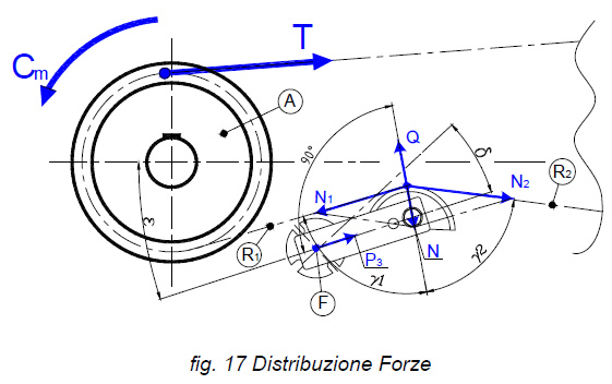
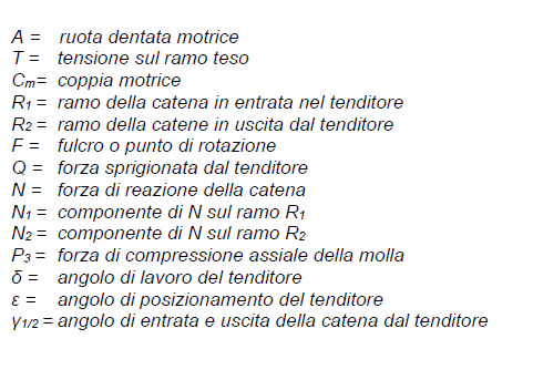
A tensioner releases a force Q (fig 17) perpendicular to the rotational arm that, by reaction, is balanced by the chain with the force N which is distributed with the traction forces N1 and N2 on the sections entering and leaving the tensioner, respectively R1 and R2. When positioning a chain tensioner, you must ensure that the forces Q and N are as much as possible on the same line so that there is no formation of tangential components which would be discharged on the fulcrum. In case of CRESA tensionsers, these undesired tangential forces are cancelled by the P3 axial compression force of the rubber spring. The positioning of the tensioner therefore depends on the angle δ, that is the working angle of the elastic element, and on the angle ε, that is the positioning angle with respect to the transmission. So the designer must find the right ratio between these parameters according to the geometry of his transmission.
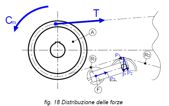
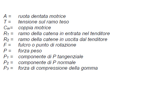
Figure 18 shows the influence of the weight force P of the chain on the tensioner in horizontal transmissions. The chain weight, especially in chains with high specific weight by meter and with long distance between centres of transmission sprockets, is divided on the tensioner into force P2 normal to the lever and a force P1 tangential to the lever. This compression element is balanced by the rubber-spring compression force P3.